
Welcome to the second lab in E5, where you will learn your way around the Machine Shop in the basement of Papazian (next to Hicks). You will be using the shop to fabricate some simple components for the robot class project, but first you must learn the basics of how to use the machines correctly and safely. Our machinist is Grant Smith, who goes by the name of Smitty. Please pay attention to his overview of the machine shop during lab period this week and next.
For the "galumphing robot" project, I have put you in the following lab groups based on the interview information you supplied in lab last week:
| Lab A | Lab B | Lab C |
Group A1:
|
Group B1:
|
Group C1:
|
Group A2:
|
Group B2:
|
Group C2:
|
Group A3:
|
Group B3:
|
|
Group A4:
|
|
Your group should plan to use the first part of lab next week to cut the board that will form the robot's base, as well as fabricate the sheet aluminum pieces to hold the wheels and contact switch. This week, after the shop overview, you should return to Trotter 201(Lab C and Lab A) or Hicks 213 (Lab B), select the components described below, and try to get the servos working. If you don't have time to do so in lab this week, feel free to come to Hicks 213 when it is free and work through the steps below. The parts will be in the E5 cabinet.
The robot you will design and build will be controlled by a computer using servos. Servos are motors that rotate through a total angle of approximately 180° to a specified angular position (-90° to +90°), as determined by the temporal length (duration) of a square-pulse voltage between 0 and 5 volts. For instance, a pulse of 1.52 ms (milliseconds) duration, repeated every 14 to 20 ms, will cause the arm of the servo to remain at the 0° position; one of 0.6 ms will cause rotation to the maximum counterclockwise position (-90° as seen from above); one of 2.4 ms will cause rotation to the maxium clockwise position (90°). In this lab, we will learn to control the 3 servo motors that will be used in the robot's crawling arm. Commands to the servos are sent from the computer's serial port, through a wireless Bluetooth link, to a Lynxmotion servo board. The Bluetooth wireless links should be paired already (if not, let a wizard or professor know, or go through the procedure for pairing them yourself). The "1" Bluetooth unit should be placed in the computer's COM1 port and powered via a USB power cable connected to its side; the "2" unit will connect with the Lynxmotion board and is powered from it.
Here is a top view of the Lynxmotion servo board:
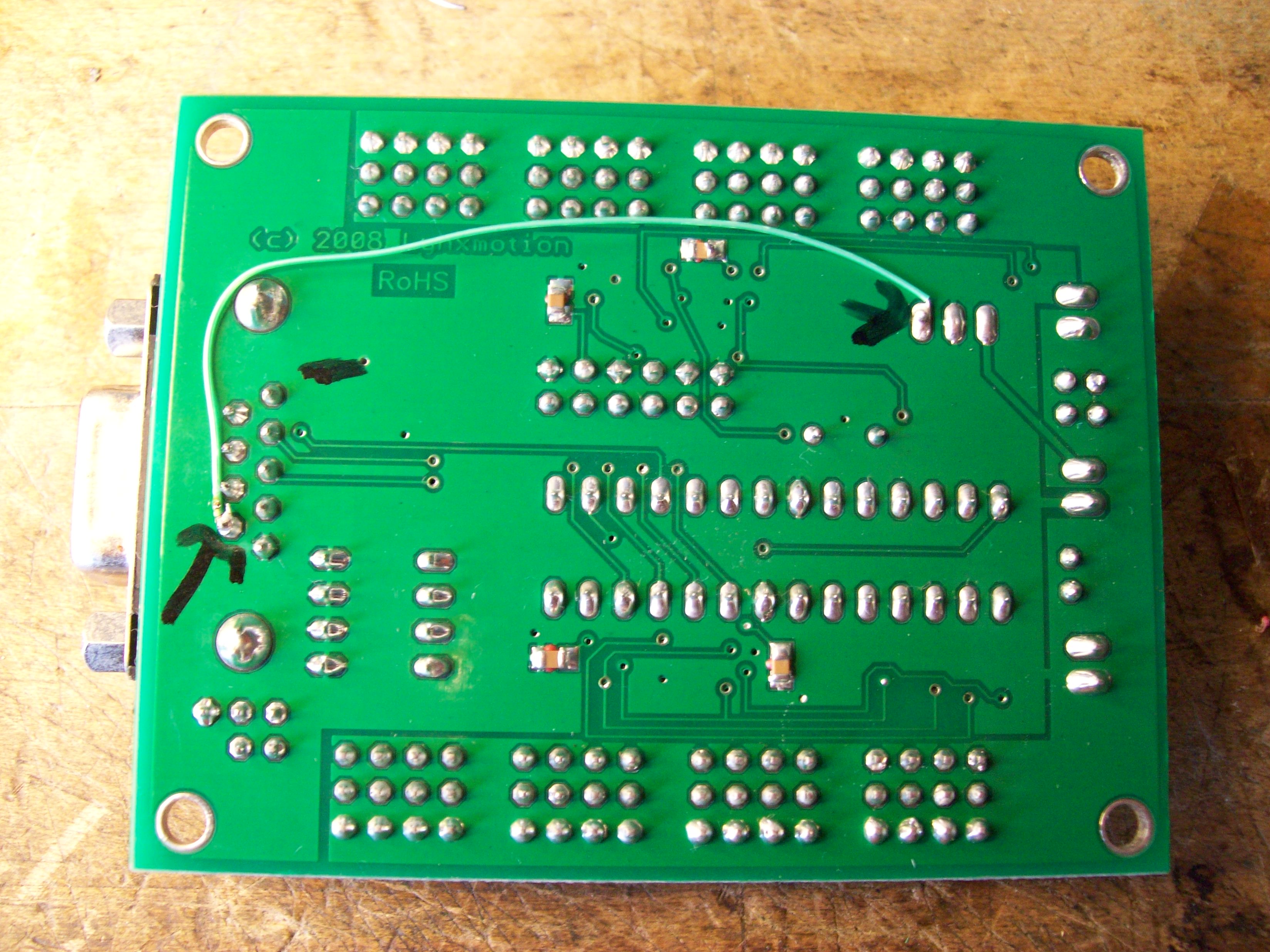
And its underside shows a wire soldered to connect Pin 9 of the Bluetooth connector to the 5V supply of the servo board:
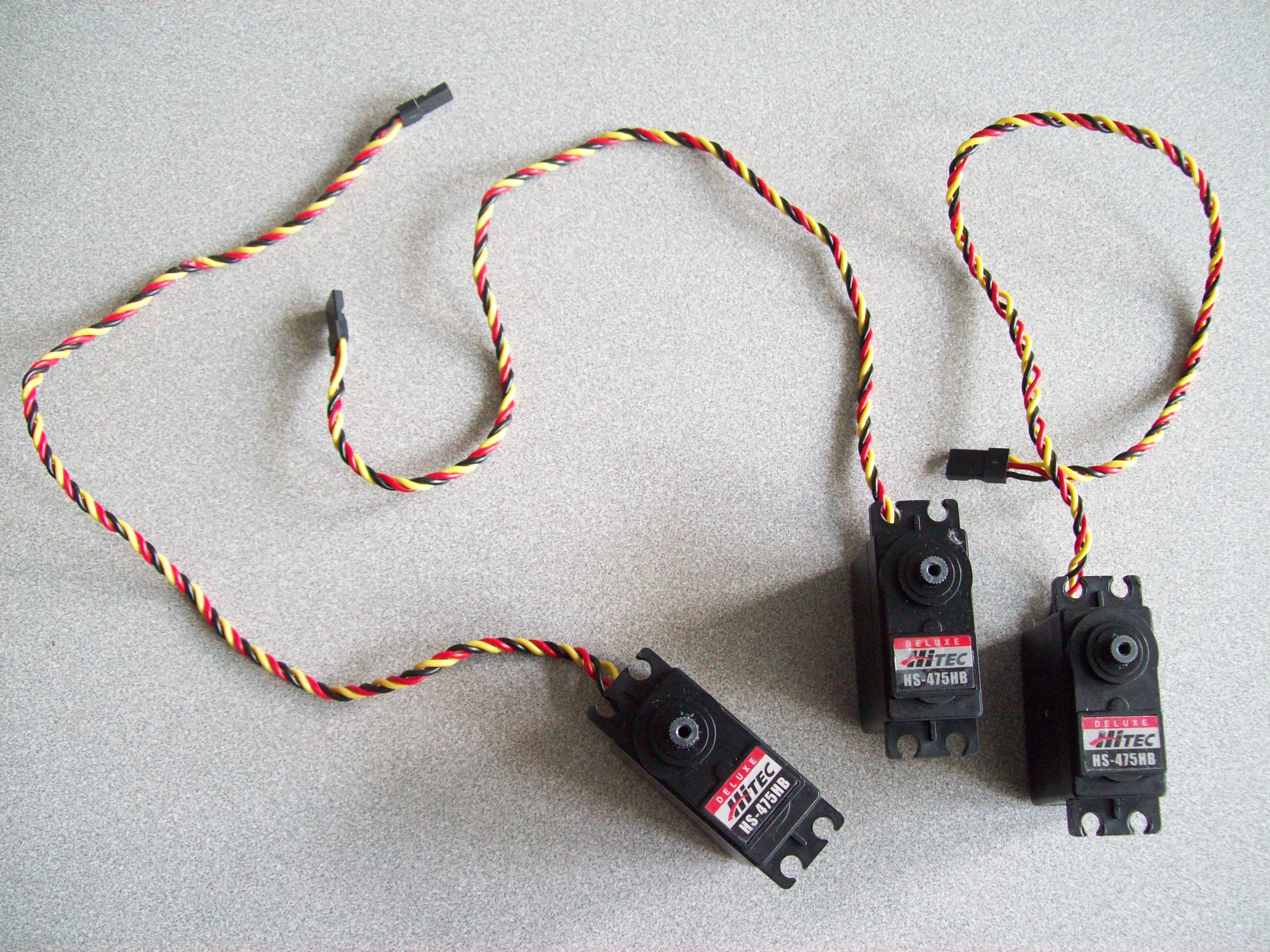
Here are the 3 servos:
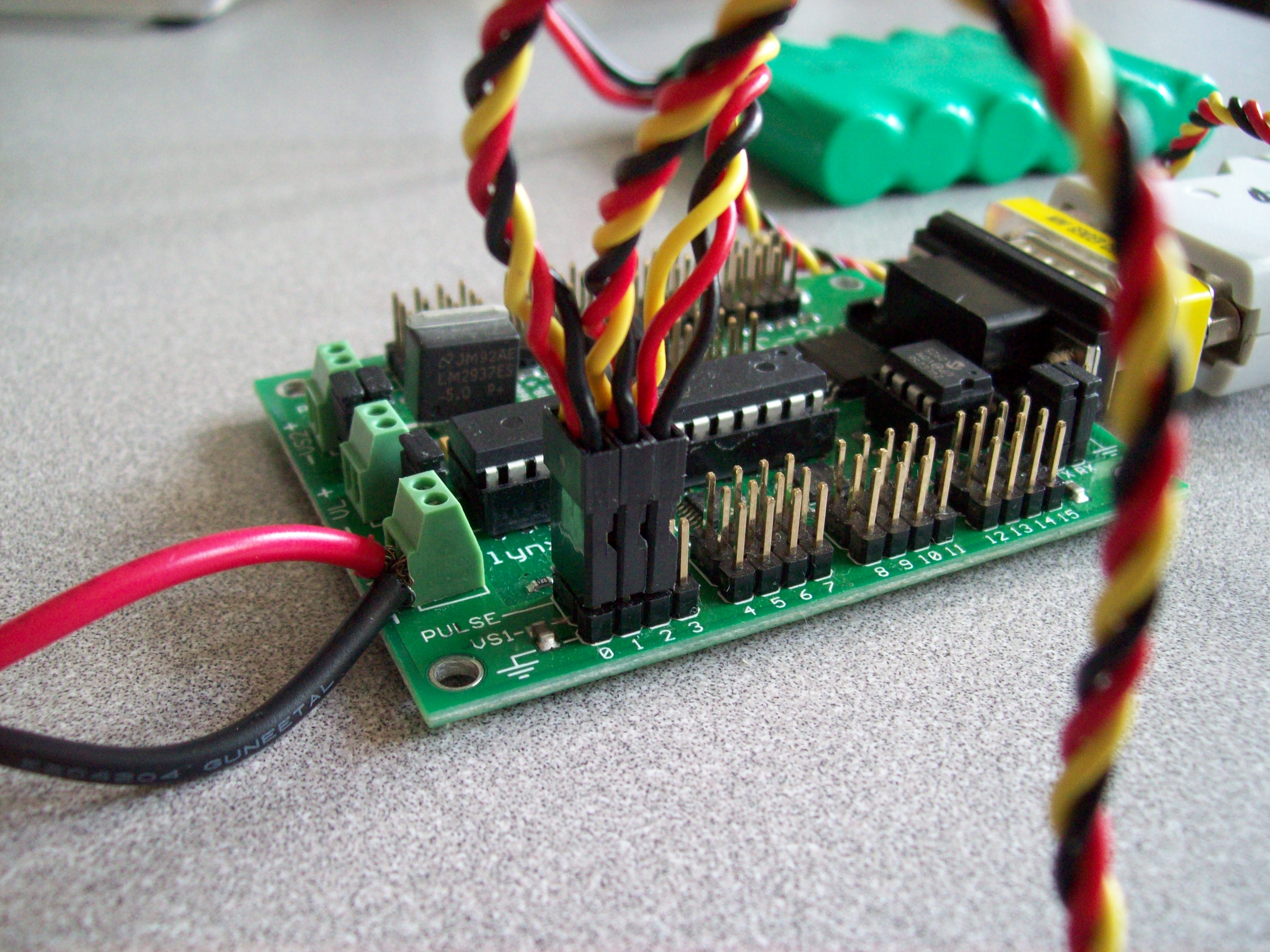
And how they connect to the servo board (locations 0, 1, and 2). Please make sure that the black (ground) wire is to the outside of the connector:
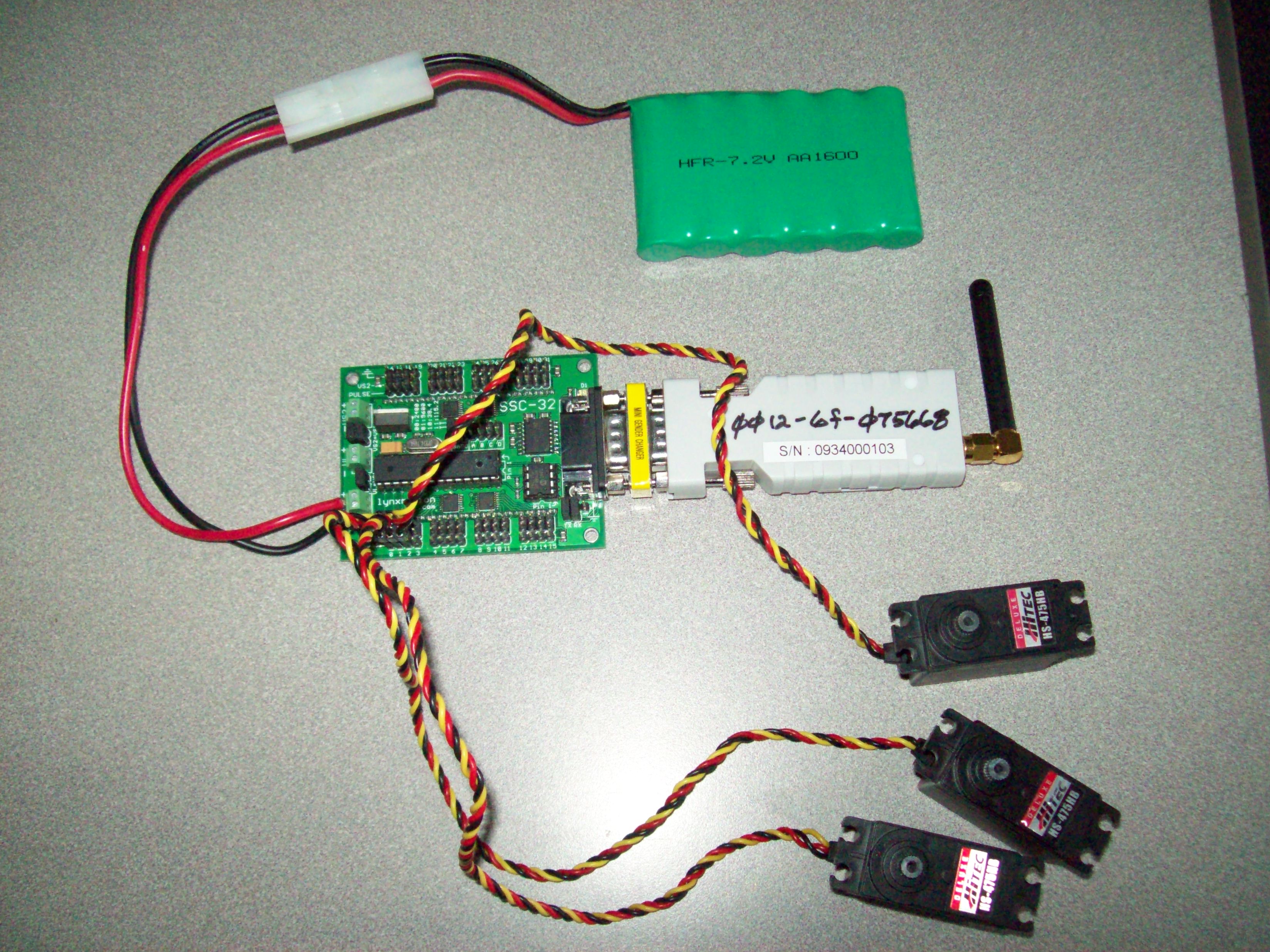
The battery pack clips onto the servo board and a green LED shows it is on. The Bluetooth receiver "2" connects through an adapter to the DB9 connector on the servo board:
If the blue lights on both the paired Bluetooth wireless serial devices are on continuously, they have synchronized and you can proceed to make the computer control the servos, as follows:
Next week we will fabricate and assemble the robot in lab, and begin to program it using Matlab commands that send strings such as "#0P1500" out of the computer's serial port to the servo controller.
|
Comments
or Questions? |
|
 |